Defender Clock
By Maui Systems Ltd

Somewhere along the lifeline of the van, someone had mangled the adjust buttons on the clock and every so often, one of them would stick itself in the case. Merrily driving along, the clock hands would now start spinning. A bit of prodding would normally free the button to stop it, but twice a year when the clocks change, it was always a lottery how long it would take to reset it.
A new clock is a mere £370 (!) and while we could probably find a third party one or a second hand one cheaper, could we make one ourselves? To be fair, we’d seen a new small round LCD display had become available, and we’d not really found a job that justified getting one to play with.
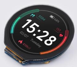
Small round LCDs

Resolution is only 240x240, but since it’s also got a touchscreen, we should be able to pair it to a microcontroller and make a decent clock. Having the touchscreen also means we can maybe add some extra features; digital, analogue or maybe something else. At around £30 for the display, we’ve still got around £340 to find a controller before we are ‘over budget’.
Controller
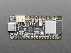
For the controller, we needed something relatively small, but with enough i/o pins that we can use for the LCD and touchscreen interfaces. It’s a clock, so only really needs a low powered controller; but thinking forward a bit, why not get it to sync via NTP so we don’t have to have ‘adjust’ buttons at all? That means some kind of network, and since the ESP32 chips have WiFi onboard, saves us having to invent some esoteric radio protocol. There are quite a few mini-esp32 boards, but without the required # of pins available. We like the ‘Adafruit’ ethos and have used their ‘feather’ range before for a number of small jobs. The ESP32 Feather V2 gives us plenty of space and power, plus also has BLE onboard for a future enhancement possibility.

Power Consumption
Once the display arrived, we could quickly set it up on a prototyping board and test things out with a spare microcontroller. Unlike the original clock, we decided that the display should be turned off when the ignition was off, but even with the display off, the power draw on the board was still too high to be on the battery 24/7.
The ESP32 has various modes of power saving, as does the display and the touchscreen. Despite quite a few attempts, we couldn’t get the power draw down to what the spec sheets say, keep the internal clock running and also be able to re-energise things reliably. It may be a problem we come back to but instead we went down a diffent route.
The orignal clock takes a permanent 12V supply; but there are plenty of switched 12V supplies in the dash too. The clock will only come on when the ignition is switched on - which matches what we wanted anyway.
To keep the time, we have a small DS3231 Real Time Clock (RTC) connected to the Feather via a QT connector. The RTC has it’s own backup battery, so when the microcontroller boots, it gets the current time from the RTC. When we do connect to WiFi and sync with an NTP server, we update the RTC accordingly. No adjust buttons - if we think the time is wrong we either switch on the van WiFi, or we just sit next to the office WiFi and it’ll correct itself.
The battery in the DS3231 should last a couple of years - at which point we will have to excavate it from the dash to change it, but by that point we may have found a similar board with a rechargeable battery.
Clock Housing
So far we’ve proved it could be done with the electronics on a bench, but there was still the issue of how we actually fit it to the dashboard; preferably in a way that made it look like it wa supposed to be there.

The display has a slight stepped edge around the perimeter, so when it’s located in the printed mount, it fits snuggly and doesn’t fall out forwards. We then printed a cylinder to fit onto the back of the mount which can hold the feather and the RTC board, but this still left us with a whole bunch of cables to fit in there and knowing where our van goes, they were never going to remain attached for long.
Interface Board
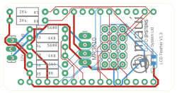
To keep things connected while the van is driven, we opted to tidy up the myriad of cables and designed our own feather shaped interface board. This reduced the overall space needed to house things and also let us slot in the other bit that we’d overlooked - a power supply. The van uses 12V power and the microcontroller needs 3V. A small voltage regulator was mounted on the interface board and we also added one more ‘feature’.

The clock will actually only be on with the ignition, so if we turn the ignition on but don’t start the engine we see the battery voltage. Once started, we can see the alternator voltage while it charges things (and let us check the alternator is working); a dual function voltage gauge no less.
Gallery
Yes it fitted, yes the 3D printing worked a charm and as expected, we ended up making a couple of refinements once installed. Mainly around the response of the touchscreen which you only really find out once you use it day to day.
Room For Project Scope Creep
The van has a secondary (leisure) battery system, so we can use some of our equipment without affecting the main starter battery. We can see the voltage of the main battery and the state of the alternator, but the secondary battery voltage is invisible.
We could run a second cable to the clock from the secondary battery system, but we use a Victron Battery Protect to make sure we don’t discharge things beyond a safe limit and the Victron device can report the voltage via BLE… which the ESP32 can do also. So the opportunity exists to get the dashboard clock to read the secondary battery voltage wirelessly.
Initial test threw up a small problem - which was the Feather microcontroller didn’t have enough space for all the extra libraries we needed to make it actually use BLE. We’re leaving this as a job for another day; maybe another ESP development environment may be better, or some trimming of libraries to get rid of bit we don’t use… For now, we have a working clock again so original project scope completed.