Genvex Heat Recovery #2
By Maui Systems Ltd
Why are we doing this?

Couriers Deliver
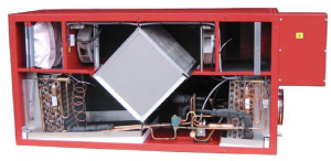
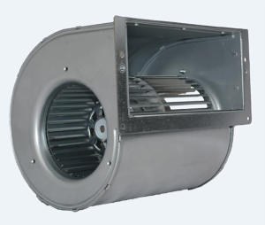
Our original Genvex heat recovery unit had a failed fan which is now obsolete and difficult to source. We used a replacement unit from the same manufacturer that came with some extra features. Primarily, instead of having to vary the voltage to adjust the speed, the fan has a speed control function with a fixed 240VAC input voltage.

A quick bit of coding got us a 4KHz signal from a spare Raspberry Pi, and when we rigged it up on the bench, the fan merrily altered it’s speed in line with the PWM signal. The one notable item was that the fan works on 10-15V signals, where a the Raspberry Pi uses 3.3V logic, so a level shifter was needed - and one that could handle the high side voltage.
Other than GND, a 10V supply and the PWM input, the fan also has a tachometer output, giving a pulse for every revolution, making it easy to work out the fan RPM. Although not necessary, this adds to the ability to monitor the health of the fan in service. When we apply a PWM signal, we should see the RPM alter accordingly. The pulse on the fan is driven from an open collector circuit, so we don’t need any logic level conversions to get it into the Pi.
The Rebuild
With new fans tested and working on the lab bench, it was time to get them fitted to the actual chassis. Some dry fitting to get the new mounting hole locations marked out then drilled and they could be mounted in place. The chassis already had mains power cabling for the original units, but needed extra ones for the new data signalling. While we were running those, we also pulled in another cable for some digital sensors (thermostats, humidity etc).
All the existing cables came into the box on the right hand side of the main unit, so the new ones were taken to the same place. As the original control board wasn’t going back in, the mounting plate for the control board was also removed to give us a bit more space to play with.
We used a Raspberry Pi (3B+) to dry run the interface to the fans, and for now, we’ve opted to continue to use it. We may switch this to a microcontroller once all the controls are sorted, but for the time being, a Raspberry Pi is easier to develop the control processes on. For the compressor and solenoid relays, we used a ‘power relay hat’ for the Pi. This made getting access to the PWM pins a bit more tricky, so it was into the PCB design software and a simple interface board was made to sit on top of the exposed relay hat header. This gave us some proper connectors for the 2 fans and the other sensor inputs.
Lastly, the digital sensors. Dallas Semiconductor One-Wire sensors are easy to work with and can sit on a bus, so that’s what we’ve used. Adding temperature sensors to each section of the chassis and options to add humidity if we need them. Rather than straight into the GPIO pins, we’ve opted to go for a USB One Wire adapter; purely because we had one and already had code from another project we could re-use.
Additional Sensors

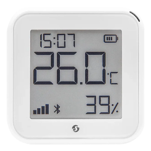
Even running the extract fan at half speed did end up having a noticable effect on the house temperature. It’s extracting any warm air 24/7 after all, This means that we need temperature and humidty data from around the house, so we went for the Shelly H+T sensor, battery powered and able to feed readings into our home network.
Next Steps
All the intial work on the bench was done with small snippets of test harness code. A unified bit of code now needs to be written to manage and monitor this device. We know the fans work so that’s the easy bit; the heat pump in the bottom of the unit has so far largely been ignored, so that needs run and the sensors connected to it observed to see how they react.